What is a 3D model?
We will explain how to define a 3D model in terms of its geometry and which kind of information is required for plotting such models with Matlab. We will learn how to define a 3D Model and the appropriate Matlab functions to show it in your screen.
1. Define a 3D model
You can find on the web plenty of 3D model files (many of them free). These files can be any object you can image but they have always an associated format ( .obj, .off, .stl, .ply, .fbx) that encodes the geometric information needed for representing a 3D object (follow this link for more information).
You can find several modeling softwares (Blender, Maya, Solidworks, etc.) that allow you to build your own models. Once you design your 3D model, you can save it in one of the previous formats according to your final goal (engineering, 3D printing, videogames, etc.). Here we focus on how to load and visualize these models using Matlab. Once you download a model, you can use MeshLab to visualize and change formats.
The simplest way to define a 3D model is to configure two tables:
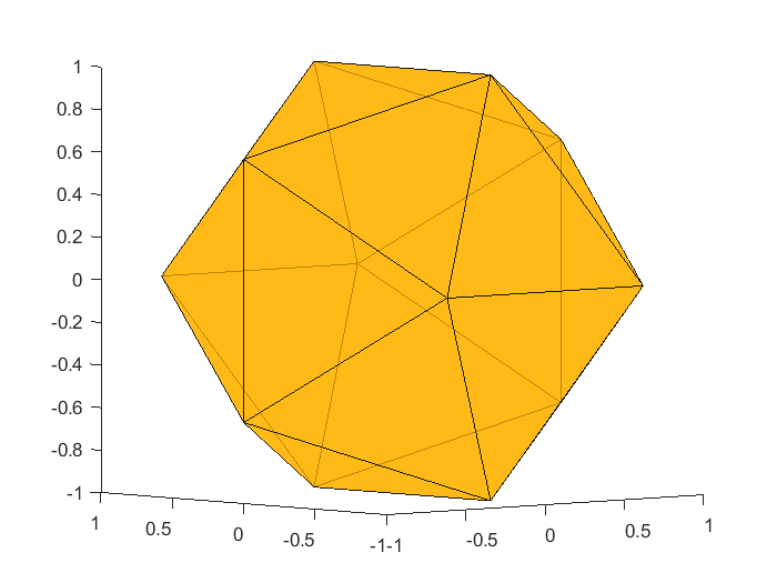
- vertices: A list of 3 values (the coordinates). Generically a Nx3 matrix containing the (x,y,z) coordinates of each of the N vertices. Below you have the vertices associated to the above icosahedron figure.
vertices=[
1.000000, 0.000000, -0.618034 ;
1.000000, -0.000000, 0.618034 ;
-1.000000, -0.000000, 0.618034 ;
-1.000000, 0.000000, -0.618034 ;
0.000000, -0.618034, 1.000000 ;
0.000000, 0.618034, 1.000000 ;
0.000000, 0.618034, -1.000000 ;
0.000000, -0.618034, -1.000000 ;
-0.618034, -1.000000, -0.000000 ;
0.618034, -1.000000, -0.000000 ;
0.618034, 1.000000, 0.000000 ;
-0.618034, 1.000000, 0.000000 ;
];
- Faces: The relationships between the vertices that define a polygon. It is known also as the connectivity matrix and it is a Fx3 matrix with F, the number of faces, and 3 columns. The second matrix dimension depends on the number of vertices per polygon (in our case triangles). Below you can see the faces defined by an icosahedron, where each row indicates which vertices are involved in each triangle.
faces=[
2, 10, 1 ;
1, 11, 2 ;
1, 8, 7 ;
1, 7, 11 ;
1, 10, 8 ;
5, 2, 6 ;
10, 2, 5 ;
2, 11, 6 ;
4, 9, 3 ;
3, 12, 4 ;
5, 6, 3 ;
3, 9, 5 ;
6, 12, 3 ;
7, 8, 4 ;
4, 12, 7 ;
4, 8, 9 ;
5, 9, 10 ;
6, 11, 12 ;
7, 12, 11 ;
8, 10, 9 ;
];
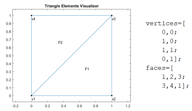
Example: Here you have a 2D example with only two triangles and four vertices.
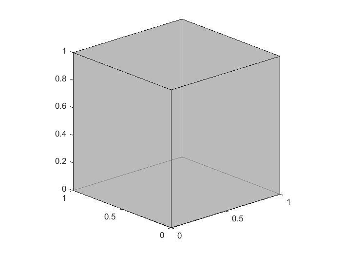
Exercise: A simple exemple is to build a cube using its vertices and faces. In this case the number of vertices is 8 and the number of faces 6 (four vertices each one).
Obs. It is important to realize that only the surface of the model is needed for visualization, what means that your model is empty, that is, no inside volume is involved. You can use a similar approach if your model is made by tetrahedra or other volum elements.
2. How to use Matlab to show a 3D model
Once you have defined the two previous tables, you have all the required information to build a 3D model. Matlab offers the patch function (see the documentation) that allows us to plot a 3D model in a Matlab window. The syntax for generating our first icosahedron figure (using the two tables defined above) is:
patch (‘Vertices’, vertices, ‘Faces’, faces, ‘FaceColor’, [1.0, 0.7, 0.0], ‘EdgeColor’, [0.1, 0.1, 0.1], ‘FaceAlpha’, 0.7);
The vertices matrix can be a Nx2 or Nx3 table according to the dimension where our model is defined. The table faces can have also 3 or 4 columns if the polygons are triangles or quadrilaterals.
The Facecolor and EdgeColor are coded using float color RGB ranging from 0.0 to 1.0. The FaceAlpha states for transparency of the face, ranging also from 0.0 to 1.0.
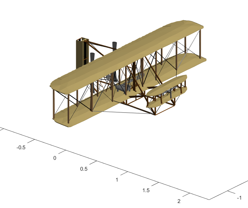
Following this link you can find many free 3D models that you can use.
3. Surface representation of a FEM solution
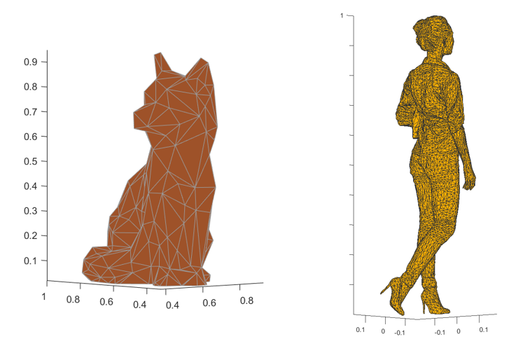
One simple 3D model is obtained by the representation of the solution of a FEM 2D problem like the ones we use in our Finite Element Course (see the post). One can represent the temperature surface as a 3D value obtained for each point using the appropriate vertices and faces.
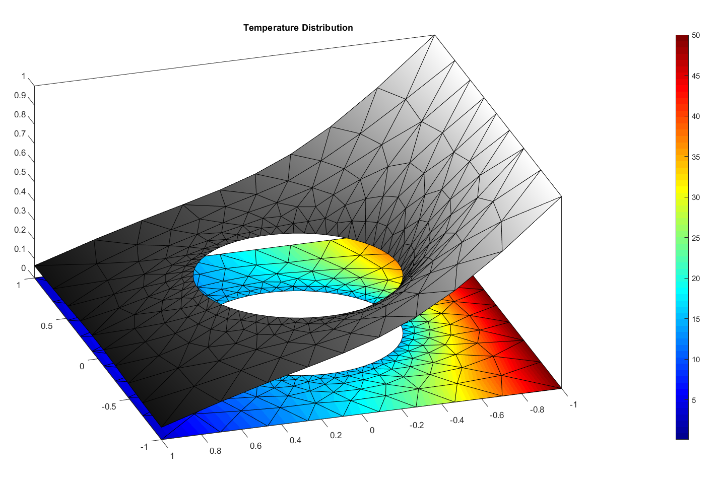
Of course you can have nicer plots if you play with illumination and other computer graphics tools, like the one shown below, but this needs a future complete post (see the nice work of Willian Harwin as example).
Views: 4644